
Bachelors in Mechanical Engineering
Masters in Automotive Engineering (Autonomous Driving Technology)

CURRENT ROLE

Roles and Responsibilities:
- Implemented and validated pose prediction for mining trucks
- Implemented , tested and validated Object Awareness Feature for all types of Caterpillar trucks
- Implemented state machine for the trucks
- Troubleshot and debugged implemented features
- Tested the features on ECM and prototype
- Refactored different features and sensor data display
- Worked on camera diagnostics
On contract
June 2021 - Present
PREVIOUS PROJECTS
Project | 01


The main objective of this project is to build a prototype for an High Speed Autonomous racecar for Indy Autonomous Challenge that took place in October 2021.
Some of the tasks that were undertaken:
- Created the systems requirement document and derived functional requirements.
- One of the main tasks assigned to me was to come up with the software architecture that will allow the communication between high-level and low-level control systems.
- The rules of the race and requirements were listed down and a state machine was formulated and implemented
- Actively took part in coming up with the startup sequence of the car as well as coding up the ROS2 C++ packages for the vehicle interface.
- Performed FMEA for software to enable emergency mode
- Tested and validated the implemented code piece on the prototype
- A speed of 180 mph was achieved in autonomous mode
Project | 02

UAV + UGV
The main objective of this project is to integrate the working of Unmanned Aerial Vehicle (UAV) with Unmanned Ground Vehicle (UGV).
The UAV captures the image feed which will be processed and used by the UGV.
Various Motion Planning techniques are currently being tested to find the optimized method for this purpose.
Project | 03
Implementation of simple Adaptive Cruise Control in RC car (Control)
The main objective of this project is to maintain a safe distance from obstacles. With the help of ultrasonic sensors that were mounted on the front and on the sides of the vehicle, the goal was accomplished. Kalman filter was implemented to obtain accurate distance measurements from the sensors. Steering control was carried out by implementing PID. The difference between the sensor readings on the sides were taken as error input to the PID and steering angle inputs to the servo motor was calculated. For maintaining safe distance from the obstacle, the front sensor readings were read and if it is less than a set distance, the throttle inputs were given as zero.
Project | 04
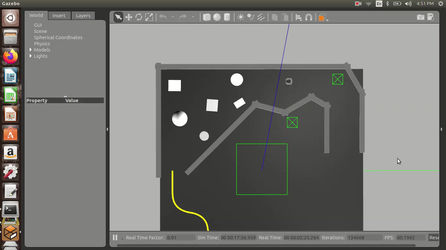

Autonomous navigation of Turtlebot in a simulated environment (ROS, open CV, obstacle avoidance and detection)
First stage: Wall following:
Lidar mounted on the turtlebot was used to find the distance of the bot from the wall and the velocity and steer angle of the bot was adjusted in such a way it maintains equal distance from the wall and steers accordingly.
Second stage: Obstacle avoidance:
The distance obtained from lidar was used to maintain a safe distance and steer away from the obstacles. The sweep from zero to 90 degrees from the center on both sides was used to determine the steer angles.
Third stage: Line following:
The camera feed was processed using OpenCV to get the centroid of the line. The steer angles of the bot were adjusted to follow the centroid of the line.
Fourth stage: STOP Sign detection:
Using the TinyYOLO dataset, the STOP sign was identified, and the velocity of the bot was set to zero for three seconds.
Fifth stage: Leg tracking
The pose of the leg was obtained and the distance from the pose was computed. The Steering and forward velocity inputs were given based on the distance between the bot and the legs.
Project | 05
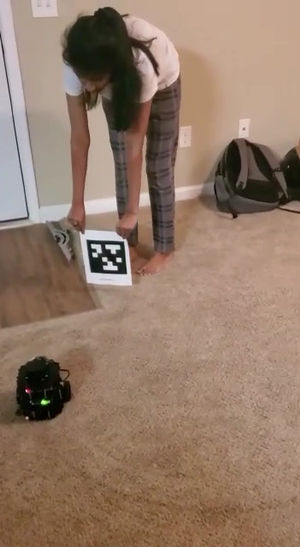
April Tag tracking:
The camera mounted on the Turtlebot was calibrated to obtain the intrinsic parameters of the camera. OpenCV was used to perform the calibration task.
AprilTag detection package was used to track the position of the AprilTag.
A simple controller to track the midpoint of the April track was used to generate steering angles for the Turtlebot
Project | 06
Collision avoidance: 3 agents, 8 agents
Distance dependent Reactive force-based approach: The distance between the neighboring agents was calculated using which the time to the collision was computed. A cost function based on the agent’s velocity and goal velocity was formulated, whose constant parameters were manually tuned, and the function was minimized to obtain the new velocity and updated.
Project | 07
Discrete planning using A star and Djikstra
A* and Djikstra motion planning algorithm was used to plan the path to a goal in the 2D grid. From the start, adjacent nodes were explored; costs and heuristics were calculated for the adjacent nodes to determine the next node.
Project | 08
PRM planner-based navigation:
Path planning for 2D objects through obstacles. Random sampling was done to create the vertices. The path from the initial position to the final position was found using the A* search algorithm.
Project | 09
Motion planning for Dubin’s car using RRT:
Implementing RRT (Rapidly-exploring Random Tree) algorithm for planning the path of a non-holonomic car (Dubin’s car model) to move from initial state to goal state. The nearest node to the new random node is chosen from the RRT available at that time. The new vertex is added to the RRT based on the set of state constraints. The distance between the tree and the random state is decided by a factor. If the random state is present at a large distance from the nearest state, another vertex is generated at a maximum distance from the nearest node in the tree along the line to the random sample. The random samples decide the direction of the tree growth while the growth factor determines its rate.
Project | 10
Autonomous Navigation using MATLAB:
Autonomous Lane Keeping: Lanes are detected using Hough transform from the camera feed. The camera was calibrated using the camera calibrator app in the MATLAB app.
Recognize road signs: Deep Learning Toolbox was used for recognizing road signs. A lot of images of the road sign were used for training the Deep learning model.
Communication: The identified road sign information was displayed in another MATLAB program. The communication between two MATLAB programs running on two different laptops was established.
Vehicle controls: Stanley controller algorithm was used to find the steering angle. HMI was incorporated to display the control commands
Project | 11


